Radar · Sensing · Signal processing
Millimeter-wave & micro-Doppler radar systems
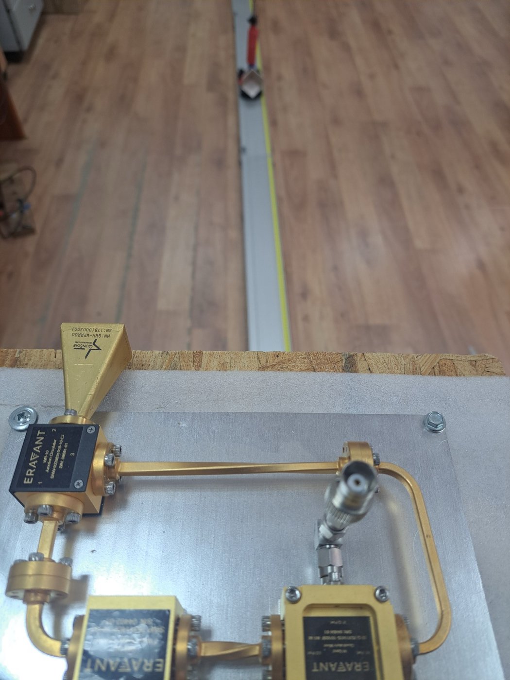
My group works on 94 GHz W-band radar. At these frequencies the short wavelength provides high phase and Doppler sensitivity to small motions; we develop radar systems and micro-Doppler processing that converts motion-induced modulations into features for target classification, combining classical estimation with machine learning.
Applications
The same core sensor and processing chain addresses a range of published and ongoing remote-sensing problems:
- Target classification & low-RCS detection: micro-Doppler signatures and machine-learning methods support classification of vehicles and other targets; ongoing work examines drone detection.
- Remote metrology: velocity-independent vehicle-height estimation from the ratio of two Doppler components, for bridge-collision prevention (Sensors 2026).
- Condition monitoring: multi-fault detection on wind turbines and rotating machinery from their micro-Doppler spectra.
- Human sensing: remote sensing of human micro-motion, including speech-related vibration (published feasibility study, Remote Sensing 2025), fall detection, and limb-movement signatures; ongoing work targets contactless vital-signs monitoring (respiration and heart rate).
Method
Work spans the full chain: waveform and antenna choices, time–frequency (spectrogram) analysis, matched filtering and high-resolution estimation, and deep-learning classifiers, implemented and validated in MATLAB, with experimental data from real W-band hardware. Antenna front-ends are designed with the same full-wave tools used for the antenna work.
Radar cross-section (RCS) modelling
How strongly a target reflects, its radar cross-section (RCS), sets received power and detectability and can contribute aspect-dependent features for classification. I compute RCS from full-wave electromagnetic scattering and, for electrically large targets, physical-optics (PO) methods, in COMSOL and MATLAB.
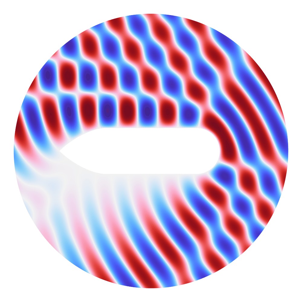
Watch the rotating-blade RCS animation →
Simulating a quadcopter’s micro-Doppler at 94 GHz
Each rotor blade moves toward and away from the radar as it turns, so the echo carries Doppler shifts up to the blade-tip speed. In a short-window spectrogram this shows as vertical blade flashes, one each time a blade crosses perpendicular to the line of sight. In a long window the same signal splits into combs of helicopter rotor modulation (HERM) lines, spaced by the number of blades times the rotation rate.
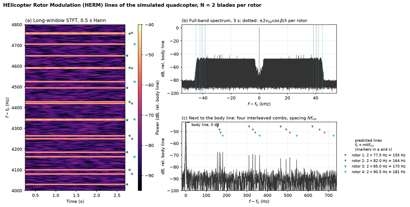
The model sums point scatterers along rigid blades (CW radar, rotors at 4650 to 5430 rpm). Its tip Doppler, flash period and line spacing match the closed-form kinematics, a check internal to the model. Blade bending and W-band measurements are covered in our paper in Sensors 26, 4851 (2026).
77 GHz automotive radar behind a bumper
An automotive radar sits behind a plastic bumper, and the panel acts as a dielectric slab. When its thickness is a multiple of half a wavelength inside the plastic, the reflections from its two faces cancel and the wave passes with little loss. At other thicknesses part of the power returns toward the radar. At 77 GHz the wavelength in the panel (relative permittivity 2.82) is 2.32 mm, so the matched thicknesses are 1.16, 2.32 and 3.48 mm.
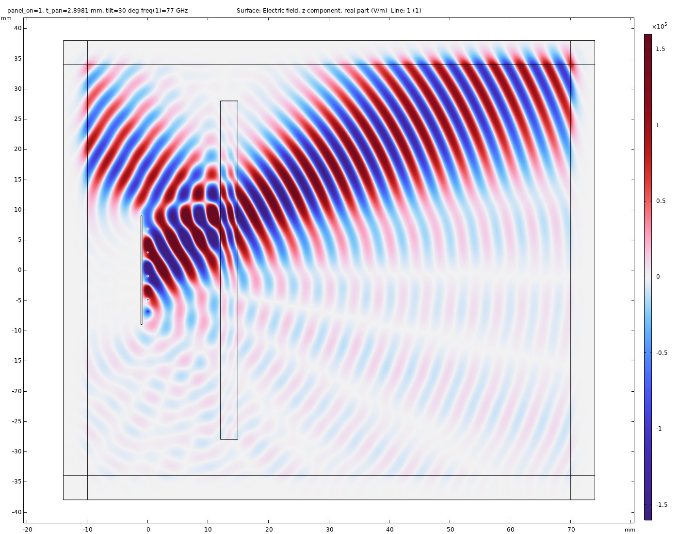
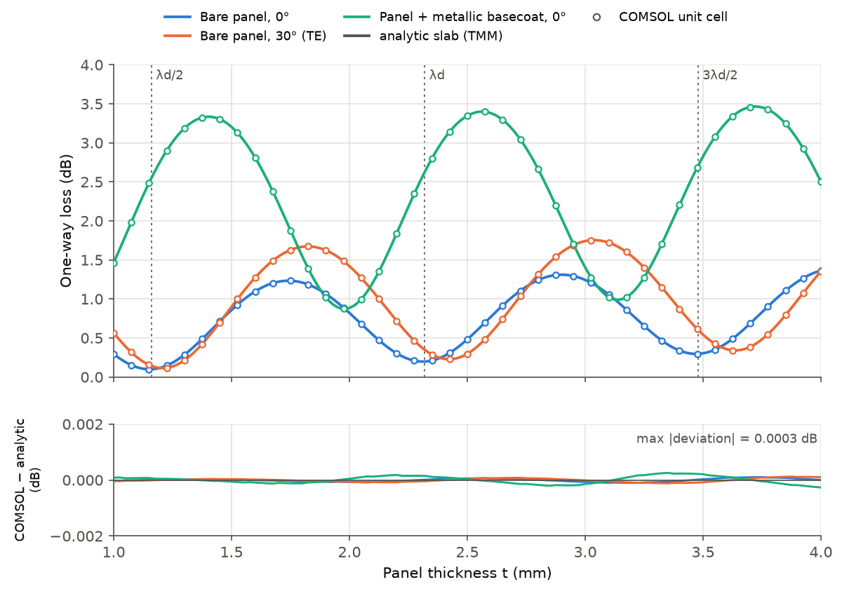
The model is 2D, for one polarization (electric field parallel to the panel), a flat panel and a single frequency. The panel and paint permittivities come from measurements of single samples in a Chalmers University of Technology diploma thesis (E. P. Emilsson, 2017). The agreement with the analytic slab verifies the numerical solution; the material data are a separate source of uncertainty.
Selected radar publications
- Balal Y, Steinmetz N, Sherenzon A, Balal N. Bending-Aware Spectrogram Correlation for W-Band Quadcopter Detection: A Physics-Informed Non-Coherent Detection Framework. Sensors 26, 4851 (2026). doi:10.3390/s26154851
- Steinmetz N, Magori E, Balal Y, Sudai YB, Balal N. A 94 GHz Millimeter-Wave Radar System for Remote Vehicle Height Measurement to Prevent Bridge Collisions. Sensors 26, 1921 (2026). doi:10.3390/s26061921
- Steinmetz N, Balal N. Feasibility Study of Real-Time Speech Detection and Characterization Using Millimeter-Wave Micro-Doppler Radar. Remote Sensing 17, 91 (2025). doi:10.3390/rs17010091
- Richter Y, Balal N. High-Resolution Millimeter-Wave Radar for Real-Time Detection and Characterization of High-Speed Objects with Rapid Acceleration Capabilities. Electronics 13, 1961 (2024). doi:10.3390/electronics13101961
- Richter Y, Balal N, Pinhasi Y. Neural-Network-Based Target Classification and Range Detection by CW MMW Radar. Remote Sensing 15, 4553 (2023). doi:10.3390/rs15184553
- Balal Y, Yarimi A, Balal N. Non-Imaging Fall Detection Based on Spectral Signatures Obtained Using a Micro-Doppler Millimeter-Wave Radar. Applied Sciences 12, 8178 (2022). doi:10.3390/app12168178
- Balal Y, Balal N, Richter Y, Pinhasi Y. Time-Frequency Spectral Signature of Limb Movements and Height Estimation Using Micro-Doppler Millimeter-Wave Radar. Sensors 20, 4660 (2020). doi:10.3390/s20174660
Applied research and technical capabilities
- Radar signal processing and micro-Doppler analysis
- Target classification and performance evaluation
- Radar cross-section and scattering simulation
- MATLAB algorithm development and experimental-data analysis
- Feasibility and proof-of-concept studies
Technical questions and research collaboration: nezahb@ariel.ac.il